THESIS
This work is dedicated to Zachary Carrico.
During the course of this project, several people contributed to its success. Paul Radja helped with the initial design and prototyping. Tom Compton helped debug the circuits. Michael Hamman helped design software and created compositions with the Composite Voice Synthesizer.
I thank Doctor Ricardo Uribe for continually advancing the Advanced Digital Signal Laboratory: an environment in which award-winning projects take place through education.
Table of Contents
List of Figures
- 2.1. Composite Voice Synthesis.
- 3.1. Block Diagram of the Composite Voice Synthesizer System.
- 3.2. Pipeline Stage Diagram.
- 4.1. Block Diagram of DSP with Peripherals.
- B.1. DSP Top Level
- B.2. DSP Memory
- B.3. Digital Signal Processor
- B.4. Seven-Segment Display
- B.5. The ISA Bus
- B.6. The Index Counter
- B.7. Pipeline Top Level
- B.8. Pitch-to-Phase Converter
- B.9. Phase Adder
- B.10. Cosine Look-Up Table
- B.11. Multiplier-Accumulator
- B.12. Phase Registers
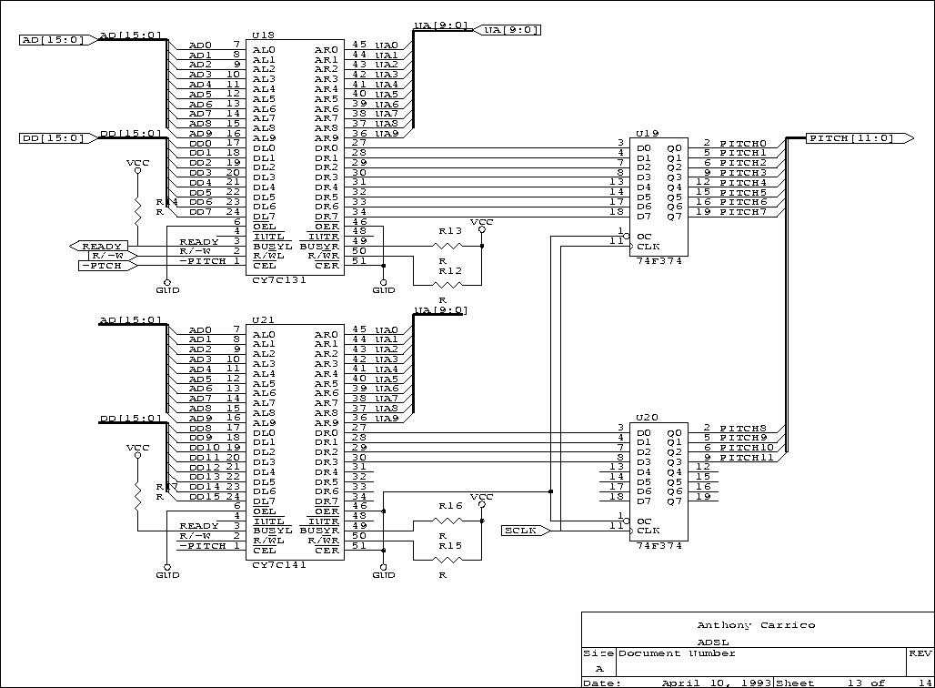
- B.13. Pitch Registers
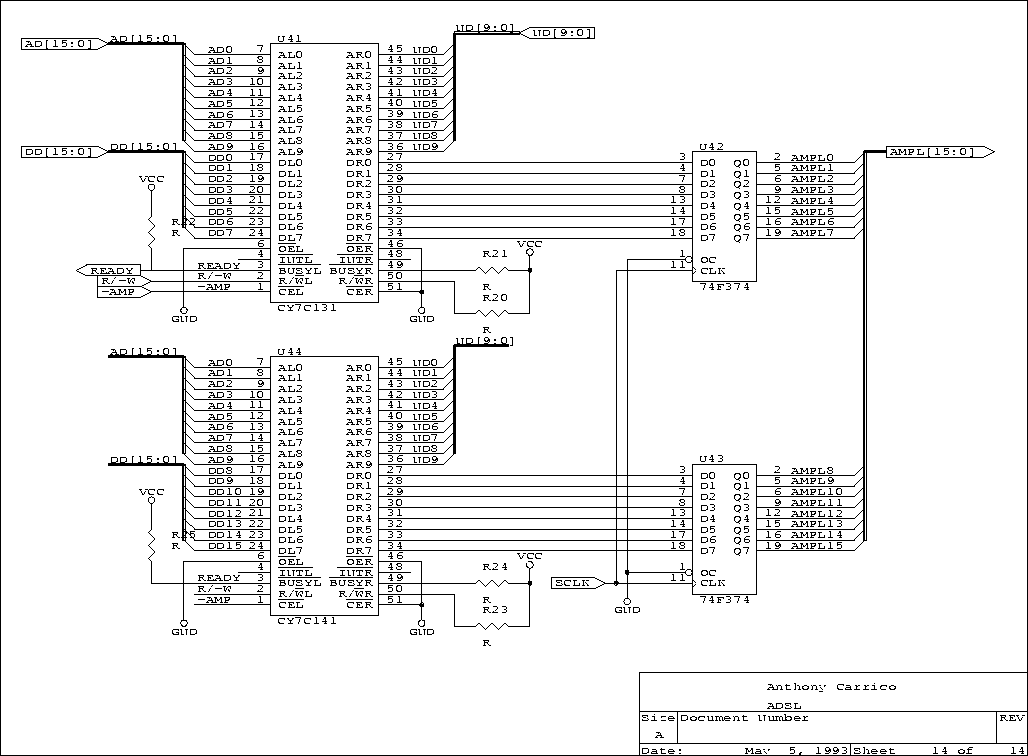
- B.14. Amplitude Registers
- C.1. The AES-EBU Converter Box
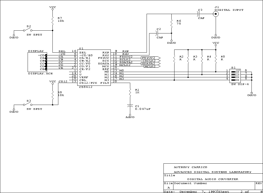
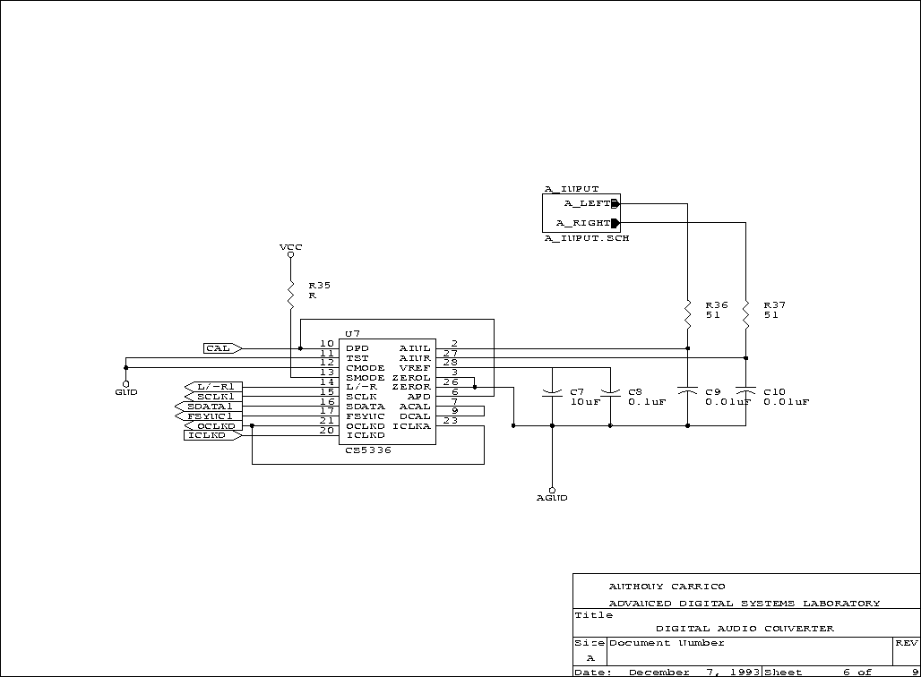
- D.1. Digital Audio Converter
- D.2. Digital Receiver
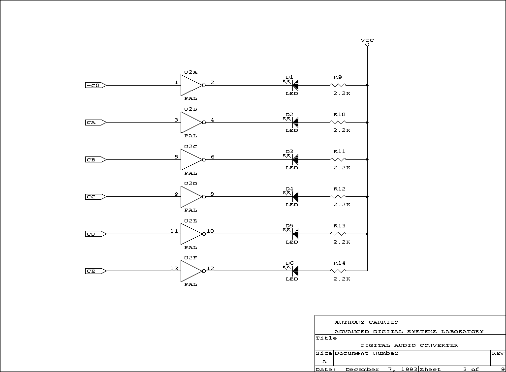
- D.3. Display
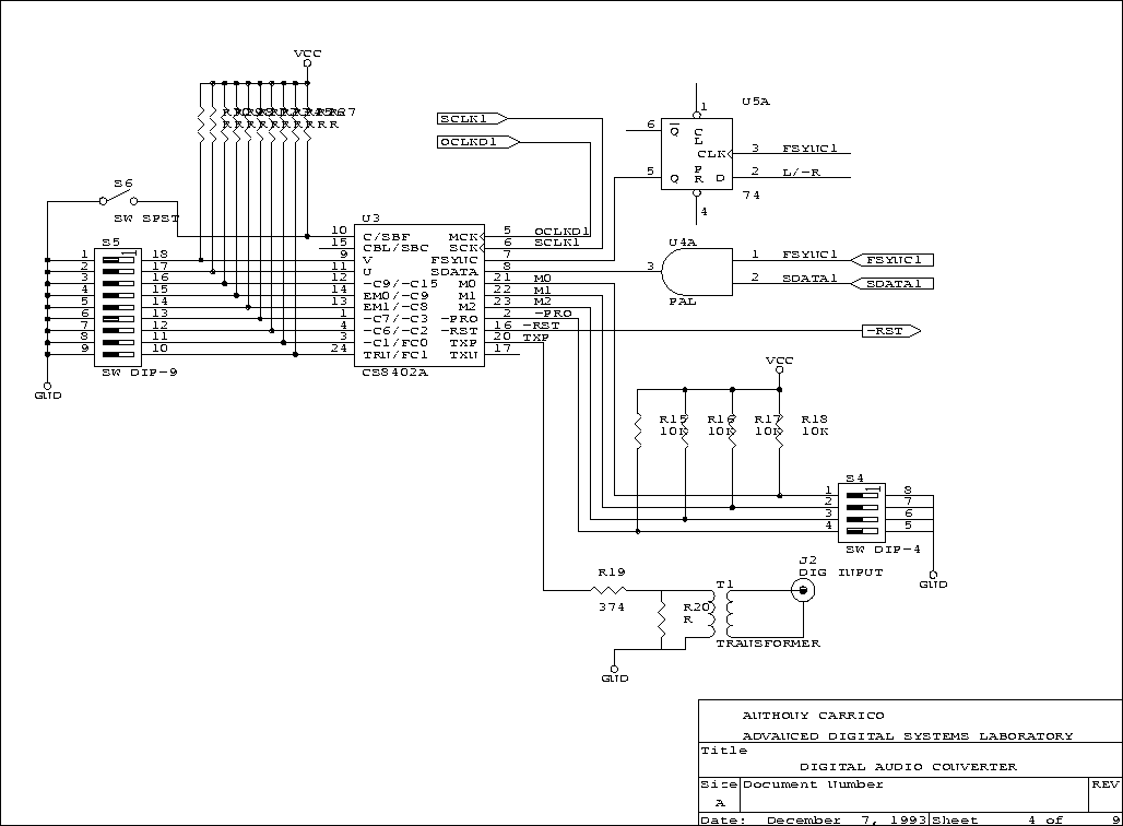
- D.4. Digital Transmitter
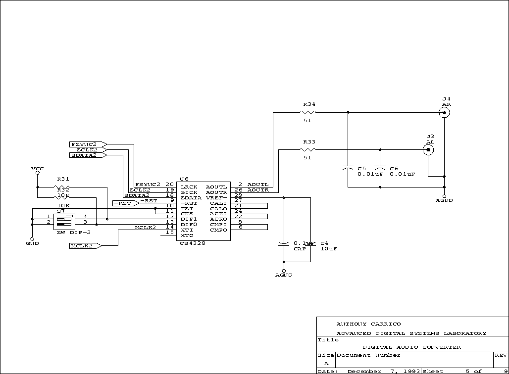
- D.5. Digital-to-Analog Converter
- D.6. Analog-to-Digital Converter
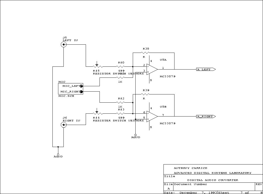
- D.7. Analog Input
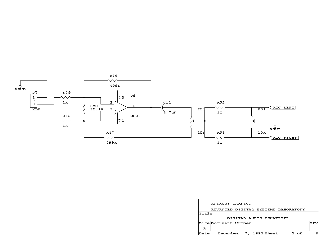
- D.8. Microphone Input
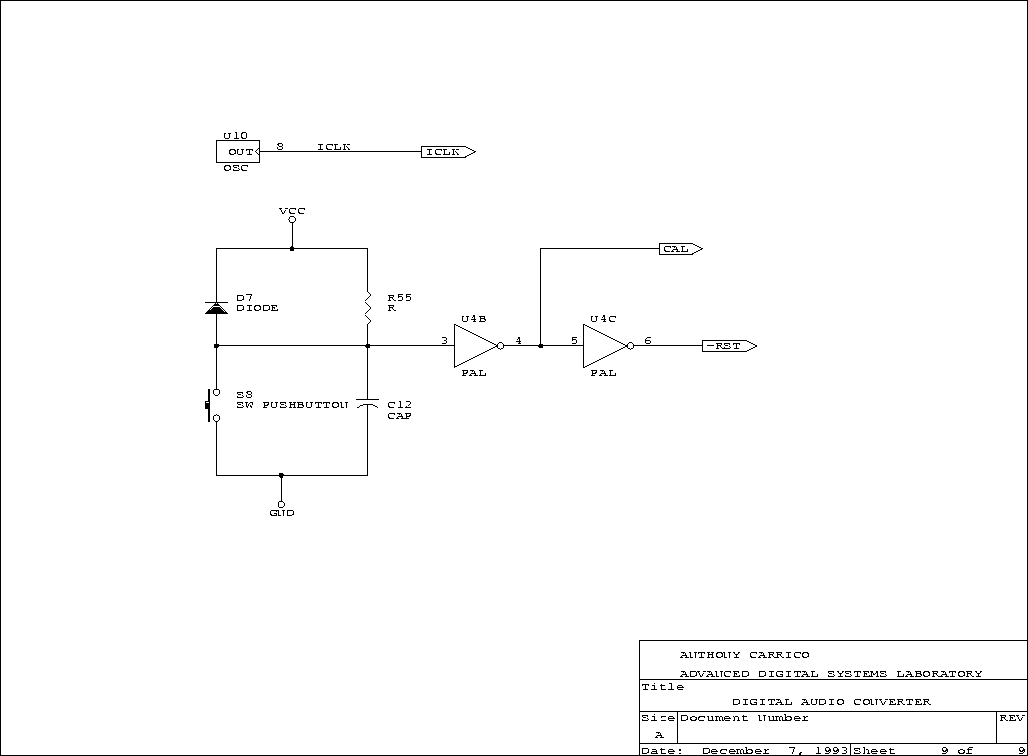
- D.9. Reset and Clock
- E.1. ms-synth.pds
- E.2. ms_dec.pds
- E.3. synthmsc.pds
- E.4. counter.pds
- F.1. voices.h
- F.2. main.c
- F.3. voice.asm
- F.4. inst.asm
- F.5. env.asm
- G.1. Memory Map
The Composite Voice Synthesizer (CVS) is a sine wave generator and a digital signal processor (DSP) with an AES-EBU (Acoustical Engineering Society, European Broadcast Union) digital output. The project also includes a Digital Audio Converter that provides bidirectional conversion between two-channel AES-EBU data and two-channel analog signals.
The intended use of the CVS is the exploration of real-time sound synthesis and music composition. The real-time nature of the CVS distinguishes it from disk-storage based computer music systems, and the composite nature of the CVS distinguishes it from other real-time synthesizers. These distinctions are made in design, but they are also a matter of application; certainly the CVS is capable of traditional real-time synthesis or computer music.
The CVS was designed and built in the Advanced Digital Systems Laboratory: A learning environment which makes the CVS available to students with diverse interests. This ensures its further development and use as an instrument for research and learning for years to come.
Table of Contents
In acoustic musical instruments, a fixed number of voices are available at one time. A piano has 88 voices available, and each produces only one pitch. A saxophone has one voice available, but that voice produces many pitches and timbres. These instruments generate the sound for each voice independently; each voice on an acoustic instrument is a separate hardware oscillator such as a string, reed or membrane. This arrangement makes up the instrument's voice structure.
Designers of electronic musical instruments adopted this same approach. Most electronic instruments output several voices that produce many pitches and timbres. Electronic instruments either duplicate the sound synthesis hardware for each voice, like acoustic instruments, or multiplex the synthesis hardware in time to produce several independent voices. In either case, there is a fixed voice structure.
A composer may desire to use more voices than are available on a particular instrument. Gathering several instruments together is one way to provide more voices, but this may not be feasible during composition. Assembling the sound on disk or tape before listening also allows more voices, but the delay involved disrupts the feedback necessary for composition. These compromises arise because electronic instruments dedicate most of their hardware to the computationally intensive task of independent voice synthesis. In an article on additive synthesizer design, Snell suggests an application of his synthesizer [Snell77] “The 256 sinusoidal components might be utilized in generating 16 voices or instruments, each having 16 partials.” This independent voice structure dominates the design and application of most real-time music synthesizers.
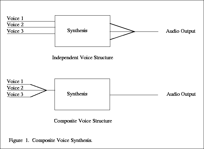
Composite Voice Synthesis is a paradigm for designing instruments that diverge from the traditional model; this allows the composer a greater range of activities and research. The CVS overcomes independent voice limitations by moving the voice structure before synthesis. A composite voice is made of the sounds from an arbitrary voice structure and the synthesis hardware synthesizes the resulting single voice (Figure 2.1).
The composite voice reduces the computational load of synthesis making the instrument's resource use more efficient and flexible. The synthesizer can use its full synthesis hardware on a small number of voices or exploit pychoacoustic effects to synthesize a larger number of voices than an independent voice structure would allow (Appendix A, Masking).
The CVS's scope is limited to spectral interpolation and synthesis, not analysis or sequencing. Ideally, the CVS would synthesize the composite voice of a preprocessor that could also help design or analyze voices; however, the CVS's own DSP assembled all music created so far because, as yet, there is no composite voice preprocessor for the system.
Table of Contents
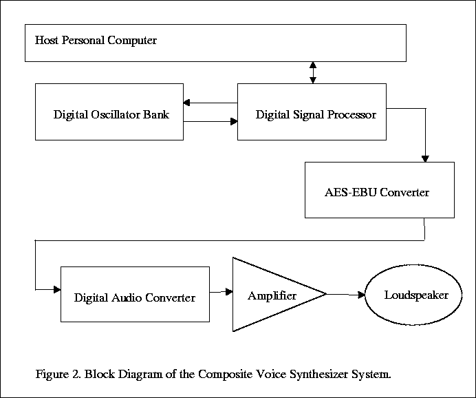
The CVS's hardware has two parts (see Figure 3.1):
- A general purpose DSP.
- A fixed pipeline processor that implements a digital oscillator bank.
This section explains the design of these parts.
The DSP is an inexpensive fixed-point processor. It features a hardware multiplier that is necessary for signal processing. The processor also interfaces easily with the output circuitry of the CVS. The flexibility of this programmable processor allows for easy experimentation with the oscillator bank.
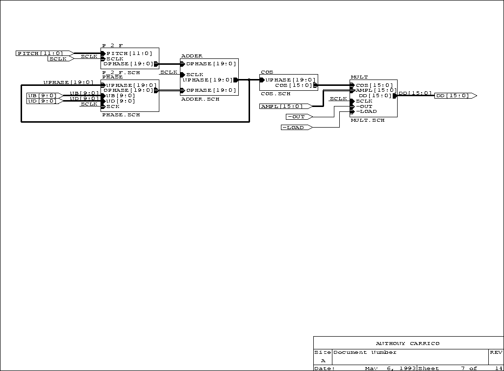
The digital oscillator bank is a pipeline that converts amplitude and pitch arrays to sound samples (Xn) according to its dedicated function:
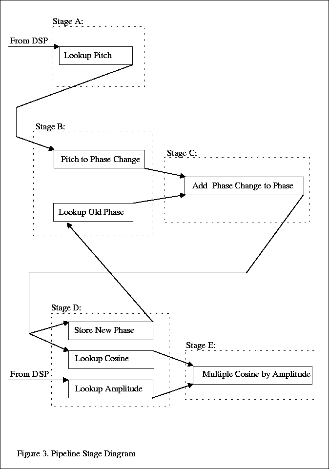
The pipeline calculates each cosine in the following phases diagrammed in Figure 3.2:
- Look up pitch.
- Convert pitch to phase change -- look up old phase.
- Add phase change to old phase.
- Store new phase -- look up cosine of new phase -- look up amplitude.
- Multiply cosine by amplitude.
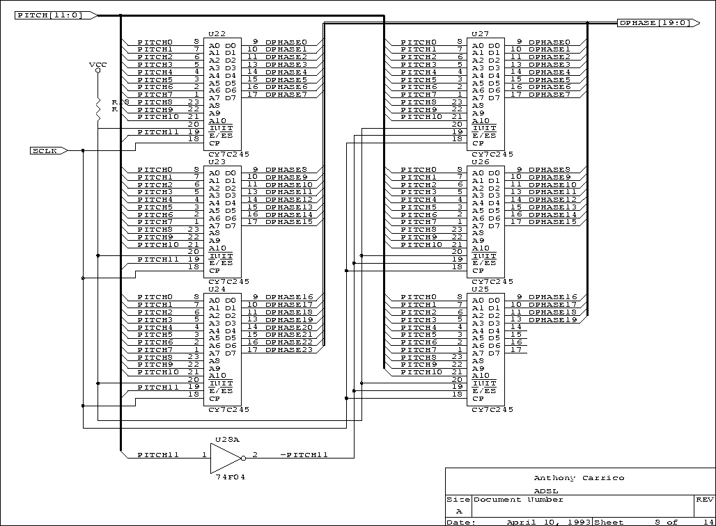
Pitch is exponentially related to frequency through the equation frequency = fref x 2pitch where fref is the reference for the exponential curve. For example, if 27.5 Hz (note A0 in musical terms) is chosen for the reference pitch, then pitch four is 440 Hz, the standard musical reference. The actual reference frequency (pitch zero) is 2-9/12 x 27.5Hz, 16.35 Hz, musical pitch C0. The following equation gives the phase change required each sample period: frequency = (change phase/220) fs, where fs is the sample frequency. A look-up table provides conversion from pitch to phase change in the pipeline. This conversion simplifies the hardware and software interfaces to the oscillator bank (see Chapter 4 and 5).
The oscillator bank uses a 16-bit word sine wave table that is 65536 (64K) words long. Noise analysis for digital oscillators presented by Moore [Moore77] indicates that this table should give an 84dB signal-to-error noise ratio (SNeR), although the reference does not contain specific noise data for this size table. The cosine function is a full 2pi wave cycle.
Table of Contents
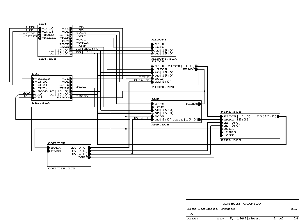
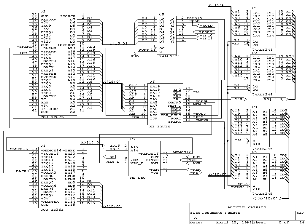
The CVS is a 16-bit card that resides on the Industry Standard Architecture (ISA) bus of a personal computer (see Figure 3.1). The circuit board is a Vector Board with power and ground planes. Physically, high-speed complementary metal oxide semiconductor (CMOS) and transistor transistor logic (TTL) parts make up the circuit. Their interconnect is Kynar wire on 3M strips soldered to integrated circuit (IC) sockets. In hindsight, the CVS should have been built with the 55 mil wire-wrapped pin technology used in other parts of the project; the 3M strips concealed several bad connections discovered and fixed during debugging. Appendix B, CVS Schematics contains the complete CVS schematics.
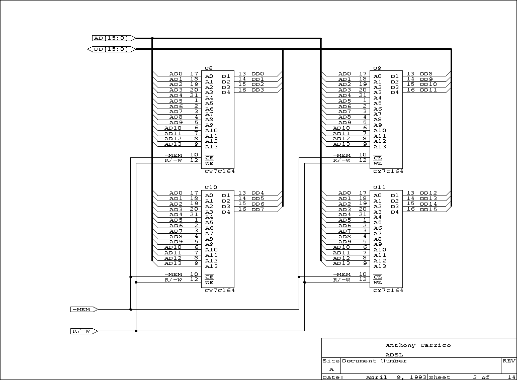
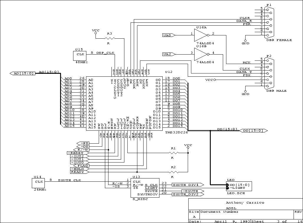
The microprocessor that controls the CVS is a 16-bit fixed point DSP (Texas Instruments TMS320C26 [TI90a]). In addition to the processor's internal processor memory, 16384 words of random access memory (RAM) are available in its external address space. The processor has a Harvard architecture with separate data and instruction spaces; however, both spaces decode physically to the same external memory: four 16384 x 4-bit static CMOS RAMs (Cypress Semiconductor CY7C164-20PC).
The DSP has a very simple, somewhat limiting, interface with its host processor (the personal computer). The host can interrupt, hold or reset the DSP through an I/O register. In the hold state, the host can directly address the DSP's external memory to examine it or load data, code and interrupt vectors. This interface allows full host downloading, monitoring and debugging capabilities, but since the host holds the DSP during these operations, real-time interaction is limited.
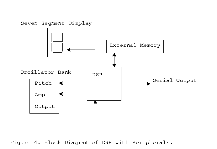
The DSP connects to the following peripherals (Figure 4.1):
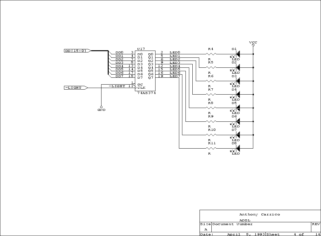
- A seven-segment LED display.
- A synchronous serial port.
- Controls for the oscillator bank's amplitudes.
- Controls for the oscillator bank's pitches.
- The oscillator bank's output register.
The seven-segment LED display facilitates hardware and software debugging. An external register latches its value and serves as a driver for the display. Simply writing to this register presents a value on the LED display.
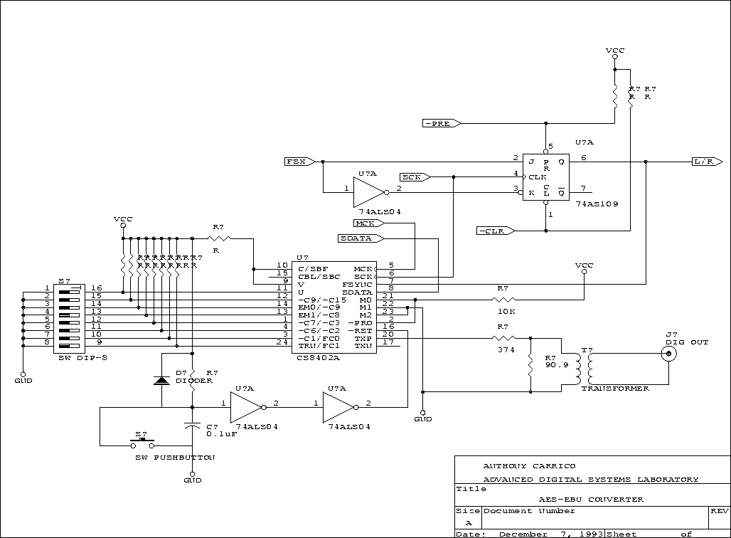
The synchronous serial port is part of the DSP integrated circuit and drives a nine-pin connector at the back edge of the circuit board. An external box (described below) converts the serial output to a standard AES-EBU digital audio output. To maintain a consistent sample rate in the system, the signal that clocks the synthesis hardware also clocks the serial port.
The DSP controls the oscillator bank through dual-port static RAM in its data memory space. This memory contains arrays for amplitude and pitch. As the DSP manipulates these arrays, the oscillator output immediately reflects the changes. The DSP reads these oscillator output samples from a register mapped in to one of its ports.
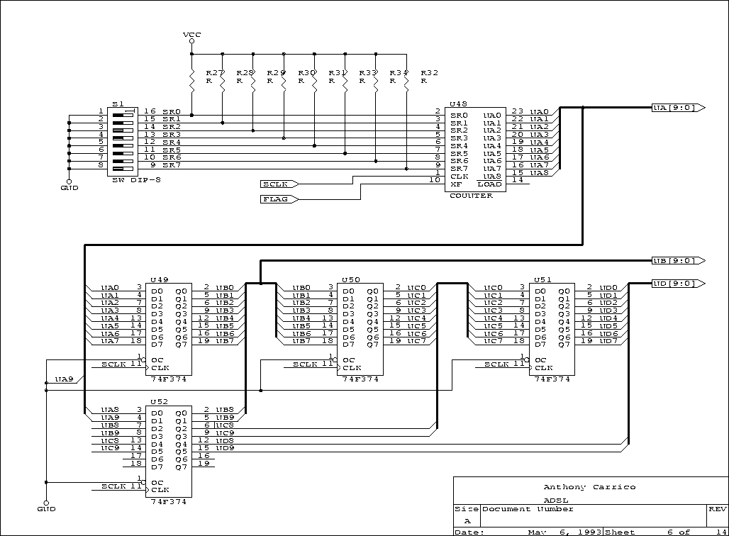
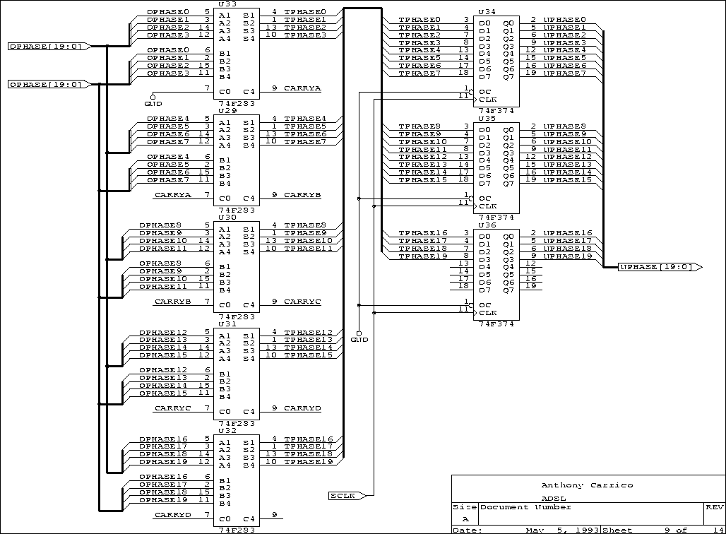
The oscillator bank is a pipeline constructed from discrete registers, memories and logic. The pipeline implements one oscillator, but an index counter, made from a programmable logic device (PLD), time multiplexes the pipeline. The index counter uses the pipeline to sum up to 512 cosines each sample period. Discrete registers and integrated pipeline registers separate the pipeline phases. The implementation uses the following components:
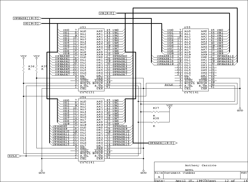
- Pitch array -- dual-ported static RAM.
- Pitch-to-phase change converter -- erasable programmable read only memory (EPROM).
- Phase accumulators -- dual-ported static RAM and TTL adders.
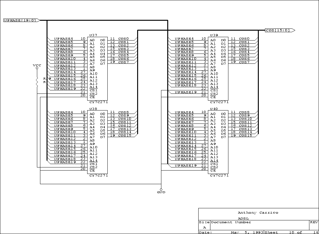
- Cosine table -- EPROM.
- Amplitude array -- dual-ported static RAM.
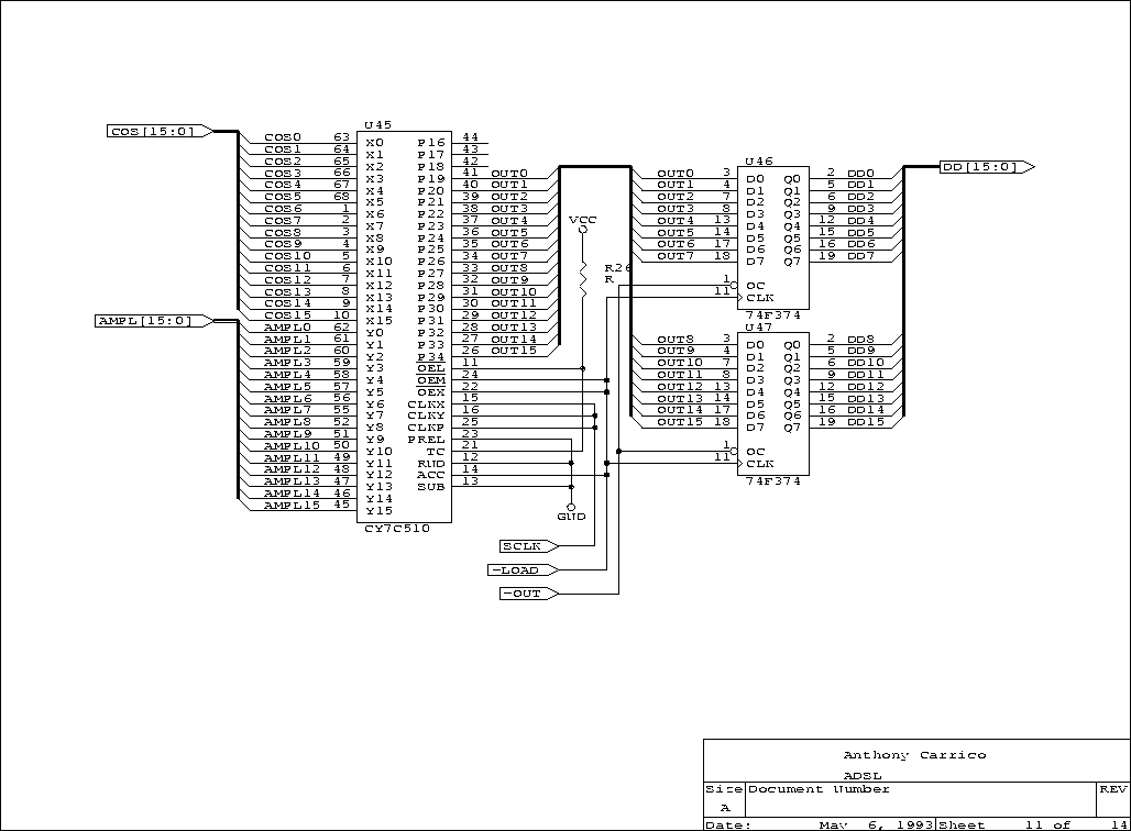
- Multiplier accumulator -- VLSI component.
The data path widths (the number of bits) vary across the pipeline. The oscillators store phase in 20-bit accumulators. Low frequency resolution and full frequency range mandate this wide path in a single sample rate system; however, a 12-bit pitch specifies the 20-bit phase change used by the accumulators. The pitch-to-phase change look-up table maps this 12-bit number to a 20-bit number. The 12-bit word length requires only a single processor data bus access.
The cosine function is a full 2pi wave cycle stored in 64K 16-bit words of EPROM. This look-up table truncates the 20-bit phase output of the phase accumulator to 16 bits and maps it to a 16-bit output. The multiplier accumulator scales this value by a 16-bit amplitude and sums the time-multiplexed output values each sample period. The DSP converts the resulting samples to a 16-bit serial output stream.
The second piece of hardware in this system is the AES-EBU converter box. This converter is external because of space constraints on the CVS board. The converter uses a Crystal Semiconductor digital audio transmitter to change the DSP's synchronous serial format to the digital audio standard format. Appendix C, AES-EBU Schematics contains the AES-EBU converter schematics.
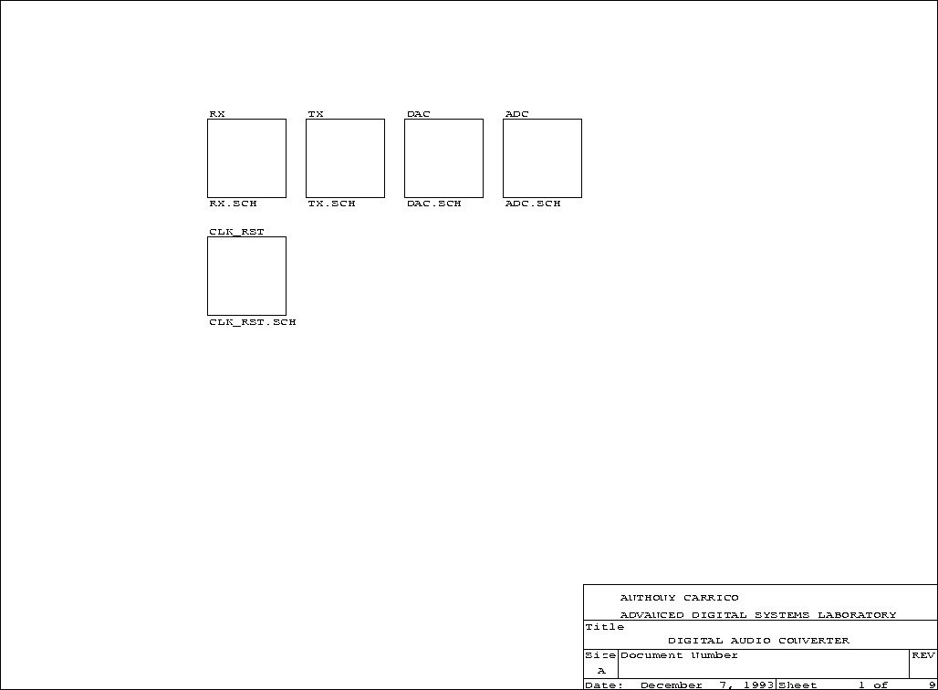
The Digital Audio Converter is the final hardware built for this system. It provides conversion between AES-EBU digital audio and line-level analog signals. It also contains a microphone preamplifier. This device uses a two-channel analog-to-digital converter with a digital audio transmitter and a two-channel digital-to-analog converter with a digital audio receiver. All of these devices are Crystal Semiconductor parts. The microphone preamplifier is based on an Analog Devices operational amplifier. This device required special attention to power supplies, ground planes, circuit layout and other factors outside the scope of this thesis. Appendix D, Digital Audio Converter Schematics contains the Digital Audio Converter schematics.
Table of Contents
Software is an important part of all programmable digital systems, including the CVS. During hardware assembly, utility software helped verify and debug the design. Later application software put the board to work.
The Texas Instruments fixed point C compiler, assembler and linker work together to produce code for the CVS's DSP. Texas Instruments provides C code for a COFF (common object file format) loader that was modified to directly access the CVS. This loader downloads program code and data to the CVS. In addition, utilities (written in C) run on the host computer to accomplish the following tasks:
- Clear the DSP's external memory.
- View the DSP's external memory.
- Reset, hold and interrupt the DSP.
This collection of programs form a monitor for developing software on the CVS.
Programs access the digital oscillator bank through two arrays mapped in specific locations of the data memory space. The amplitude array simply specifies 16-bit amplitude values. The pitch array specifies 12-bit pitches. Since this system uses pitch instead of frequency units, programs can linearly shift a sound's pitch. For instance, a sound with three harmonic elements is transposed by adding a constant to each component; the resulting pitches are still harmonic. There are two sets of amplitude and pitch arrays and the DSP's external flag determines which one of these the oscillator bank uses. This double-buffer scheme allows the DSP to change one set while the other is in use, similar to a double frame buffer in video animation.
Three critical functions are the basis of a core program that can be expanded to create musical compositions:
- DSP initialization.
- Oscillator bank control.
- Audio sample output.
This program relates the oscillator bank hardware to a software stack of pitch and amplitude envelopes. The core program is driven by serial port and timer interrupts.
When the serial port interrupt triggers, the DSP fetches a sample from the oscillator bank's output and sends the sample out the serial port. The digital audio stream expects two-channel (left/right) output, thus this sequence happens twice every sample period; currently, both channels receive the same signal.
The timer interrupt divides the processor's time into eight segments for multitasking. The DSP uses one of these segments for generating the oscillator bank's envelopes. The remaining segments can be used for composition or other sound synthesis code.
Envelope generators track the pitch and amplitude for each sine wave. At the lowest level, arrays in dual ported RAM directly determine pitch and amplitude. The envelope generators use two-level linear interpolation. A fast inner loop interpolates “breakpoints” that another routine generates from “envelope points”. Each oscillator can be assigned an arbitrarily long set of pitch and amplitude envelope points. A stack stores unused oscillators so that program code can easily allocate oscillators as necessary. When an oscillator reaches the end of its envelope, the oscillator automatically goes back to the oscillator stack.
A simple music player was the first application designed for the CVS. This player works with three data files. The first specifies envelope shapes which are combined in the second to form instruments. Finally a third file encodes notes from a staff. Parts of two musical pieces were entered into this player: a Bach invention and a Beethoven quartet (Appendix F, Software). These serve as a demonstration of the system; however, data files for this player are tedious to generate.
Michael Hamman [Hamman93], who helped write the core synthesis program, experimented with code for music composition on the CVS. His own words describe this work:
The program “Core-Dump” uses the CVS to explore fixed-point numeric processing algorithms which nevertheless display complex and unpredictable behaviors. The program implements a network of simple “modulus” functions of the sort x = (y * m) MOD n. By experimenting with different networks and observing their (audible) results, networks were implemented which favored output behaviors that are extremely sensitive to initial conditions and which can vary considerably over time as the system is running. The program defines a network of value-less nodes. The values which determine the connections between nodes and which determine the system's output values (those used by the oscillator) are determined at run time. The system uses 128 of the 512 oscillators available on the oscillator bank. The program is designed to run continuously (“forever”), producing sequences of sounds as it does so. Different input data result in completely different resultant behaviors. Typically changes in the sound sequences can occur suddenly and without transition. This characteristic behavior traces the behavior of the software generating it: certain “regions” of order emerge and persist for some time and then suddenly change revealing either a new region of order or ever-varying regions of disorder.
When is a project done? There is no satisfactory answer, but there are several aspects of this project that merit further exploration. The focus of this work was hardware design and implementation, but the idea of Composite Voice Synthesis deserves research for its own sake.
Within the framework of this project, a second component could be built to process and transfer spectral data to the CVS. This device would combine instrument sounds and reduce the resulting spectrum according to psychoacoustic masking principals. Also, future signal processing experiments in the Advanced Digital Systems Laboratory can make use of the Digital Audio Converter built for this project.
Outside of this project researchers should develop other real-time synthesizers using the Composite Voice principle, instead of classical voice structure. Finally, engineers and other technical people who develop tools should collaborate with composers on design and application, a path chosen in this project. The results of such collaboration will surprise and delight.
Masking inherent in the human hearing mechanism locally reduces the ear's dynamic range in frequency bands around spectral peaks. Several audio data compression algorithms for digital tape (Phillips) and disk (Sony) recording, digital radio transmission (Musicam) and video soundtrack storage (Motion Picture Experts Group, MPEG) rely on this phenomenon.
Haken [Haken92] designed and built a digital signal processor to investigate interpolation between sounds. He points out that auditory masking can make the sound synthesis more efficient. The computational savings available with Composite Voice Synthesis can be enhanced by taking advantage of masking effects.
The following pages contain the complete Composite Voice Synthesizer schematics.
The following pages contain the complete AES-EBU converter schematics.
The following pages contain the complete Digital Audio Converter schematics.
The following pages contain the complete equations for the system's programmable logic.
Figure E.1 | Figure E.2 | Figure E.3 | Figure E.4
Figure E.1. ms-synth.pds
;PALASM Design Description
;---------------------------------- Declaration Segment -----------
TITLE ms-synth.pds
PATTERN
REVISION 1
AUTHOR Anthony Carrico
COMPANY ADSL
DATE 03/28/92
CHIP ms_synth PAL22V10
;---------------------------------- PIN Declarations --------------
PIN 1   sa19
PIN 2   sa18
PIN 3   sa17
PIN 4   sa16
PIN 5   sa9
PIN 6   sa8
PIN 7   sa7
PIN 8   sa6
PIN 9   sa1
PIN 10  aen
PIN 11  /iow
PIN 13  /smemw
PIN 14  port          COMBINATORIAL
PIN 15  /dsp_hold
PIN 16  /dsp1
PIN 17  /dsp2
PIN 18  mem_d         COMBINATORIAL
PIN 19  /DACK0        COMBINATORIAL
PIN 20  /rw1          COMBINATORIAL
PIN 21  /rw2          COMBINATORIAL
PIN 22  /EN1          COMBINATORIAL
PIN 23  /EN2          COMBINATORIAL

;------------------------------------ Boolean Equation Segment -----

EQUATIONS

mem_d = sa19 * sa18 * /sa17 * sa16 * /DACK0
port = sa9 * sa8 * /sa7 * /sa6 * sa1 * /aen * iow
rw1=smemw
rw2=smemw
rw1.trst = dsp_hold * dsp1 * mem_d
rw2.trst = dsp_hold * dsp2 * mem_d
EN1 = DSP1
EN2 = DSP2
EN1.TRST = dsp_hold * dsp1 * MEM_D
Figure E.2. ms_dec.pds
;PALASM Design Description
;---------------------------------- Declaration Segment -----------
TITLE ms_dec.pds
PATTERN
REVISION 1
AUTHOR Anthony Carrico
COMPANY ADSL
DATE 03/28/92
CHIP _ms_dec PALCE16V8
;---------------------------------- PIN Declarations --------------
PIN 2   ada15   ;
PIN 3   ada14   ;
PIN 4   adb15   ;
PIN 5   adb14   ;
PIN 6   /DSa    ;
PIN 7   mem_d   ;
PIN 8   /strbb  ;
PIN 11  /PSa    ;
PIN 12  /mema     COMBINATORIAL ;
PIN 13  /memb     COMBINATORIAL ;
PIN 14  /amp      COMBINATORIAL ;
PIN 15  /pitch    COMBINATORIAL ;
PIN 16  /out      COMBINATORIAL ;
PIN 17  /MEMCS16  COMBINATORIAL ;
;----------------------------------- Boolean Equation Segment -----
EQUATIONS
mema= /ada15 * /ada14 * (DSa + PSa + mem_d )
memb= /adb15 * /adb14 * ( strbb + mem_d )
amp= /ada15 * ada14 * ( DSa + PSa + mem_d)
pitch= ada15 * /ada14 * ( DSa + PSa + mem_d )
out= /ada15 * ada14 * (DSa + PSa + mem_d )
MEMCS16 = 1
MEMCS16.TRST = MEM_D
Figure E.3. synthmsc.pds
;PALASM Design Description
;---------------------------------- Declaration Segment -----------
TITLE SYNTH MISC
PATTERN
REVISION 2.0
AUTHOR ANTHONY CARRICO
COMPANY ADSL
DATE 01/30/93
CHIP _SYNTHMSC PAL22V10

;---------------------------------- PIN Declarations -------------
PIN 1   CLK ;
PIN 2   r_w
PIN 3   /is
PIN 20  synthdiv  registered
PIN 21  /synth
PIN 22  /light
PIN 23  SYNTHCLK  REGISTERED ;

;----------------------------------- Boolean Equation Segment -----
EQUATIONS

SYNTHCLK = /SYNTHCLK * synthdiv + synthclk*/synthdiv
synthdiv = /synthdiv
light = /r_w * is
synth = r_w * is
Figure E.4. counter.pds
;PALASM Design Description
;---------------------------------- Declaration Segment -----------
TITLE counter
PATTERN
REVISION 1.00
AUTHOR Anthony Carrico
COMPANY ADSL
DATE 10/04/92
CHIP _counter PAL22V10
;---------------------------------- PIN Declarations --------------
PIN 1 clk    ; CLOCK
PIN 2 sr0    ; INPUT
PIN 3 sr1    ; INPUT
PIN 4 sr2    ; INPUT
PIN 5 sr3    ; INPUT
PIN 6 sr4    ; INPUT
PIN 7 sr5    ; INPUT
PIN 8 sr6    ; INPUT
PIN 9 sr7    ; INPUT
PIN 10 xf    ;flag from dsp to tell synth to switch banks
PIN 15 na8   REGISTERED    ; OUTPUT
PIN 16 na7   REGISTERED    ; OUTPUT
PIN 17 na6   REGISTERED    ; OUTPUT
PIN 18 na5   REGISTERED    ; OUTPUT
PIN 19 na4   REGISTERED    ; OUTPUT
PIN 20 na3   REGISTERED    ; OUTPUT
PIN 21 na2   REGISTERED    ; OUTPUT
PIN 22 na1   REGISTERED    ; OUTPUT
PIN 23 na0   REGISTERED    ; OUTPUT
PIN 14 /load COMBINATORIAL ; OUTPUT
;----------------------------------- Boolean Equation Segment -----
EQUATIONS
load = na0*na1*na2*na3*na4*na5*na6*na7
na0 = /load*/na0
na1 = load*sr0
      + /load*(na0*/na1+/na0*na1)
na2 = load*sr1
      + /load*(na1*na0*/na2+/(na1*na0)*na2)
na3 = load*sr2
      + /load*(na2*na1*na0*/na3+/(na2*na1*na0)*na3)
na4 = load*sr3
      + /load*(na3*na2*na1*na0*/na4+/(na3*na2*na1*na0)*na4)
na5 = load*sr4
      + /load*(na4*na3*na2*na1*na0*/na5+/(na4*na3*na2*na1*na0)*na5)
na6 = load*sr5
      + /load*(na5*na4*na3*na2*na1*na0*/na6+/(na5*na4*na3*na2*na1*na0)*na6)
na7 = load*sr6
      + /load *(/(na6*na5*na4*na3*na2*na1*na0)*na7+na6*na5*na4*na3*na2*na1*na0*/na7)
na8 = xf
The following pages contain the complete program and some of the data to play a Beethoven quartet on the CVS.
Figure F.1 | Figure F.2 | Figure F.3 | Figure F.4 | Figure F.5
Figure F.1. voices.h
/* Anthony Carrico 2/25/93 */
/* voices.h */
/* Header for synthesizer program */

#include <ioports.h>
#include <stdlib.h>
#include <values.h>

#define numosc 128
#define n1osc 32
#define n2osc 64
#define n3osc 96
#define numenv 20
#define numvoice 22
#define numinst 20

unsigned int *prd = (unsigned int *) 3; /* ptr to PRD register */
int *amp1 = (int *) 0x4100; /* Amp Pointer */
int *pitch1 = (int *) 0x8100; /* Pitch Pointer */
int *amp0 = (int *) 0x4000; /* Amp Pointer */
int *pitch0 = (int *)0x8000; /* Pitch Pointer */
int BPamp[numosc], BPpitch[numosc];
int STEPSZ_amp[numosc], STEPSZ_pitch[numosc];
int acc_pitch[numosc], acc_amp[numosc];
int *env_table[numenv];
int *voice_table[numvoice];
int *inst_table[numinst];
int **EP_env = (int**) 0x2000;
int *EP_time = (int *) 0x2100;
unsigned int *EP_old = (unsigned int *) 0x2200;
int *EP_pitch = (int *) 0x2300;
int *EP_amp = (int *) 0x2400;
int *EP_on = (int *) 0x2500;
int *osc_stack = (int*) 0x2600;
int osc_top = 0;
int VP[numvoice];
extern int env0[];
extern int env1[];
extern int env2[];
extern int env3[];
extern int env4[];
extern int env5[];
extern int env6[];
extern int env7[];
extern int env8[];
extern int env9[];
extern int env10[];
extern int env11[];
extern int env12[];
extern int env13[];
extern int env14[];
extern int env15[];
extern int env16[];
extern int env17[];
extern int env18[];
extern int env19[];
extern int v0[];
extern int v1[];
extern int v2[];
extern int v3[];
extern int v4[];
extern int v5[];
extern int v6[];
extern int v7[];
extern int v8[];
extern int v9[];
extern int v10[];
extern int v11[];
extern int v12[];
extern int v13[];
extern int v14[];
extern int v15[];
extern int v16[];
extern int v17[];
extern int v18[];
extern int v19[];
extern int v20[];
extern int v21[];
extern int inst0[];
extern int inst1[];
extern int inst2[];
extern int inst3[];
extern int inst4[];
extern int inst5[];
extern int inst6[];
extern int inst7[];
extern int inst8[];
extern int inst9[];
extern int inst10[];
extern int inst11[];
extern int inst12[];
extern int inst13[];
extern int inst14[];
extern int inst15[];
extern int inst16[];
extern int inst17[];
extern int inst18[];
extern int inst19[];
void c_int1();
void c_int2();
void c_int5();
void setup();
void env(int osc);
int init_osc();
int give_osc(int osc);
int get_osc();
void init_extern();
void trig_inst(int *inst, int amp, int pitch);
void trig_voice(int num, int event, int *voice);
void prog1();
void prog2();
void prog3();
Figure F.2. main.c
/* Anthony Carrico 2/4/93 */
/* main.c */
/* player program */
#include "voices.h"
void prog1 ()
{
  static int tick=0;
  static int event=0;
  int j;
  tick++;
  if (tick % 4 == 0)
    {
      for (j=0;j<numvoice;j++)
        {
          trig_voice(j, event, voice_table[j]);
        }
      event++;
    }
}

void trig_voice (int num, int event, int *voice)
{
  if(event == voice[ 3*(*voice) + VP[num] + 1])
    {
      trig_inst(inst_table[*(voice+ VP[num] + 1)],
                *(voice + *voice + VP[num] +1),
                *(voice + 2* (*voice) + VP[num] +1));
      if(VP[num] == *voice) VP[num]=0;
      else VP[num]++;
    }
}

void trig_inst (int *inst, int amp, int pitch)
{
  int j;
  int osc;

  for(j=0;j<*inst;j++)
    {
      osc = get_osc();
      EP_amp[osc] = ((long int) amp * *(inst+j+1)) >> 15;
      EP_pitch[osc] = pitch + *(inst+*inst+j+1);
      EP_env[osc] = env_table[*(inst+2 * *inst + j +1)];
      EP_on[osc]=1;
    }
}

void prog2() {}
void prog3() {}

/* init_osc --> put all the oscillators in the oscillator pool
            only call this once !!! */

int init_osc()
{
  int j; for(j=0;j<numosc;j++)
    give_osc(j);
  return(1);
}

/* give_osc --> give an oscillator to the oscillator pool */
/* return(1) ---> normal */
/* return(0) ---> can't return the osc */
int give_osc(int osc)
{
  if (osc_top < numosc)
    {
      osc_stack[osc_top] = osc;
      osc_top++;
      return(1);
    }
  else
    return(0);
}

/* get_osc() --> gets an oscillator from the oscillator pool */
/* returns the oscillator number or */
/* returns numosc if none available */
int get_osc()
{
  unsigned int i[11];
  unsigned int temp;
  i[0] = 33;
  i[1] = 125;
  i[2] = 38;
  i[3] = 52;
  i[4] = 120;
  i[5] = 176;
  i[6] = 160;
  i[7] = 61;
  i[8] = 32;
  i[9] = 56;
  i[10] = 0-4-128-16-2;
  if (osc_top != 0)
    {
      osc_top--;
      temp = numosc-osc_top;
      if (temp>9)
        temp=10;
      outport (0,i[temp]);
      return (osc_stack[osc_top]);
    }
  else
    return(numosc);
}

/*-------------------------------------------------------------------------*/
void main()
{
  unsigned int i,j;
  unsigned int* timerflag;
  /* interupt flag */
  timerflag = (unsigned int *) 98;
  setup();
  while (1)
    {
      for (i=0;i<8;i++)
        {
          *timerflag=1;
          /* interpolate each oscillator */
          if (i%2 == 0)
            {
              asm (" sxf ");
              for (j=0;j<numosc;j++)
                {
                  acc_pitch[j] += STEPSZ_pitch[j];
                  pitch0[j] = acc_pitch[j] >> 3;
                  acc_amp[j] += STEPSZ_amp[j];
                  amp0[j] = acc_amp[j];
                }
            }
          else
            {
              asm(" rxf ");
              for(j=0;j<numosc;j++)
                {
                  acc_pitch[j] += STEPSZ_pitch[j];
                  pitch1[j] = acc_pitch[j] >> 3;
                  acc_amp[j] += STEPSZ_amp[j];
                  amp1[j] = acc_amp[j];
                }
            }
          switch(i)
            {
              case 0:
                for(j=0;j<numosc;j++)
                  {
                    STEPSZ_amp[j] = (BPamp[j] - acc_amp[j]) / 8;
                    STEPSZ_pitch[j] = (BPpitch[j] - acc_pitch[j]) / 8;
                  }
                break;
            case 1:
              for (j=0; j<n1osc; j++)
                {
                  if (EP_on[j] == 1)
                    env(j);
                }
              break;
            case 2:
              for (j=n1osc; j<n2osc; j++)
                {
                  if (EP_on[j] == 1)
                    env(j);
                }
              break;
            case 3:
              for (j=n2osc; j<n3osc; j++)
                {
                  if(EP_on[j] == 1) env(j);
                }
              break;
            case 4:
              for (j=n3osc; j<numosc; j++)
                {
                  if (EP_on[j] == 1)
                    env(j);
                }
              break;
            case 5:
              prog1 (BPamp, BPpitch);
              break;
            case 6:
              prog2 (BPamp, BPpitch);
              break;
            case 7:
              prog3 (BPamp, BPpitch);
              break;
            }
          /* Error displays 3 on timer overrun */
          if (*timerflag != 1)
            outport(0,52);
          while (*timerflag == 1);
        }
    }
  while(1);
}

void setup()
{
  /*#define ttx (*(int *)0x01)*/
  int *tamp; /* 0x4512; Amp Pointer */
  int *tpitch; /* 0x8512; Pitch Pointer */
  int *ttx; /* serial port transmit register */
  unsigned int j,err;
  unsigned int i[10];
  i[0] = 33;
  i[1] = 125;
  i[2] = 38;
  i[3] = 52;
  i[4] = 120;
  i[5] = 176;
  i[6] = 160;
  i[7] = 61;
  i[8] = 32;
  i[9] = 56;
  tpitch = (int *) 0x8000;
  tamp = (int*) 0x4000;
  ttx = (int *) 0x01;
  for(j=0; j<1024 ;j++)
    {
      *(tamp+j) = 0;
      *(tpitch+j) = 0;
    }
  for(j=0; j<numosc; j++)
    {
      EP_env[j] = env0;
      EP_time[j]=0;
      EP_old[j] =0;
      EP_pitch[j] =0;
      EP_amp[j] =0;
      EP_on[j]=0;
      BPamp[j]=0;
      BPpitch[j]=0;
      STEPSZ_amp[j]=0;
      STEPSZ_pitch[j]=0;
      acc_pitch[j]=0;
      acc_amp[j]=0;
    }
  *prd = 48000;
  asm(" dint ");
  asm(" sfsm ");      /* set frame sync on serial port */
  asm(" stxm ");      /* set frame sync to output */
  asm(" fort 0 ");    /* 16 bit words =0 8 bit words=1 */
  asm(" sst 102 ");   /* save status reg 0 */
  asm(" ldpk 0 ");
  asm(" sar 0,100");  /* save ar0 */
  asm(" lark 0,32 "); /* 15-6 reserved 5-xint 4-rint 3-tint 2-2 1-1 0-0 */
  asm(" sar 0,4 ");   /* Store IMR interupt mask reg */
  asm(" lark 0,0 ");
  asm(" sar 0,2 ");   /* zero timer */
  asm(" sar 0,1 ");   /* start serial port */
  asm(" eint ");      /* enable serial port interupt */
  asm(" lark 0,44" ); /* 15-6 reserved 5-xint 4-rint 3-tint 2-2 1-1 0-0 */
  asm(" sar 0,4" );   /* Store IMR interupt mask reg */
  asm(" lar 0,100");  /* restore ar0 */
  asm(" lst 102 ");   /* restore status reg 0 */
  asm(" rxf ");       /* select low synth bank */
  init_osc();
  init_extern();
  for(j=0; j<numvoice; j++) VP[j]=0;
}

/*
   Envelope update routine...
   Envelope data structure:

   num_EP,
   EP_amp0, EP_amp1, EP_amp2, ..., EP_ampN,
   EP_pitch0, EP_pitch1, EP_pitch2, EP_pitch3, ..., EP_pitchN,
   time0, time1, time2, time3, ..., timeN.

*/

void env(int osc)
{
  long int cur_step;
  int time0, time1, steps;
  int *EP;

  EP=EP_env[osc];

  if(EP_time[osc] == 0)
    {
      BPamp[osc] = ((long int) EP_amp[osc] * *(EP + 1)) >> 15;;
      BPpitch[osc] = *(EP + *EP + 1);
      EP_old[osc]=1;  /* time(1) */
      EP_time[osc]++;
    }
  else
    {
      time0 = *(EP + 2*(*EP) + EP_old[osc]);
      time1 = *(EP + 2*(*EP) + EP_old[osc] + 1);
      steps = time1 - time0;
      cur_step = EP_time[osc] - time0;
      BPamp[osc] = cur_step * (*(EP + EP_old[osc] + 1)
                   - *(EP + EP_old[osc])) / steps
                   + *(EP + EP_old[osc]);
      BPamp[osc] = ( (long int) EP_amp[osc] * BPamp[osc] ) >> 15;
      BPpitch[osc] = cur_step * (*(EP + *EP + EP_old[osc] + 1)
                     - *(EP + *EP + EP_old[osc])) / steps
                     + *(EP + *EP + EP_old[osc])
                     + EP_pitch[osc];
      if (time1 == EP_time[osc])
        EP_old[osc]++;
      EP_time[osc]++;
      if(EP_old[osc] == *EP)
        {
          BPamp[osc] = ((long int) EP_amp[osc] * *(EP + *EP)) >> 15;
          EP_old[osc]=0;
          EP_time[osc]=0;
          EP_on[osc]=0;
          give_osc(osc);
        }
    }
}

void init_extern()
{
  env_table[0] = env0;
  env_table[1] = env1;
  env_table[2] = env2;
  env_table[3] = env3;
  env_table[4] = env4;
  env_table[5] = env5;
  env_table[6] = env6;
  env_table[7] = env7;
  env_table[8] = env8;
  env_table[9] = env9;
  env_table[10] = env10;
  env_table[11] = env11;
  env_table[12] = env12;
  env_table[13] = env13;
  env_table[14] = env14;
  env_table[15] = env15;
  env_table[16] = env16;
  env_table[17] = env17;
  env_table[18] = env18;
  env_table[19] = env19;
  voice_table[0] = v0;
  voice_table[1] = v1;
  voice_table[2] = v2;
  voice_table[3] = v3;
  voice_table[4] = v4;
  voice_table[5] = v5;
  voice_table[6] = v6;
  voice_table[7] = v7;
  voice_table[8] = v8;
  voice_table[9] = v9;
  voice_table[10] = v10;
  voice_table[11] = v11;
  voice_table[12] = v12;
  voice_table[13] = v13;
  voice_table[14] = v14;
  voice_table[15] = v15;
  voice_table[16] = v16;
  voice_table[17] = v17;
  voice_table[18] = v18;
  voice_table[19] = v19;
  voice_table[20] = v20;
  voice_table[21] = v21;
  inst_table[0] = inst0;
  inst_table[1] = inst1;
  inst_table[2] = inst2;
  inst_table[3] = inst3;
  inst_table[4] = inst4;
  inst_table[5] = inst5;
  inst_table[6] = inst6;
  inst_table[7] = inst7;
  inst_table[8] = inst8;
  inst_table[9] = inst9;
  inst_table[10] = inst10;
  inst_table[11] = inst11;
  inst_table[12] = inst12;
  inst_table[13] = inst13;
  inst_table[14] = inst14;
  inst_table[15] = inst15;
  inst_table[16] = inst16;
  inst_table[17] = inst17;
  inst_table[18] = inst18;
  inst_table[19] = inst19;
}

void c_int1() {} /* external interrupt 0 */
void c_int2() {} /* external interrupt 1 */
void c_int5() {} /* serial port receive interrupt */
Figure F.3. voice.asm
; voice.asm -- Voice data for Beethoven
  .global _v0
  .global _v1
  .global _v2
  .global _v3
  .global _v4
  .global _v5
  .global _v6
  .global _v7
  .global _v8
  .global _v9
  .global _v10
  .global _v11
  .global _v12
  .global _v13
  .global _v14
  .global _v15
  .global _v16
  .global _v17
  .global _v18
  .global _v19
  .global _v20
  .global _v21

  .data

  ;time is in 38.4 ms increments
  ;about 26 ticks per second

    ;voices...
    ;EV number of events
    ;EV instrument number
    ;EV amplitude
    ;EV pitch
    ;EV tick

_v0 .int 5
    .int 12, 11, 14, 11, 13
    .int 4000, 4000, 4000, 4000, 4000
    ;    a4    g4    b4    a4    c5
    .int 14840,14280,15400,14840,15680
    .int 0,    4,    8,    20,   24

_v1 .int 8
    .int 2, 1, 2, 1, 2, 1, 2, 1
    .int 4000, 4000, 4000, 4000, 4000, 4000, 4000, 4000
    ; e4 e4 g4 g4 g4 g4 a4 a4
    .int 13440,13440,14280,14280,14280,14280,14840,14840
    .int 0, 6, 8, 14, 16, 22, 24, 30

_v2 .int 8
    .int 2, 1, 2, 1, 2, 1, 2, 1
    .int 4000, 4000, 4000, 4000, 4000, 4000, 4000, 4000
    ; c4 c4 e4 e4 e4 e4 e4 e4
    .int 12320,12320,13440,13440,13440,13440,13440,13440
    .int 0, 6, 8, 14, 16, 22, 24, 30

_v3 .int 8
    .int 2, 1, 2, 1, 2, 1, 2, 1
    .int 4000, 4000, 4000, 4000, 4000, 4000, 4000, 4000
    ; c3 c4 b3 b3 b3 b3 a3 a3
    .int 8960,12320,12040,12040,12040,12040,11480,11480
    .int 0, 6, 8, 14, 16, 22, 24,30

_v4 .int 1 .int 2,2, 2, 2,2, 2,2, 2,2 .int 6000,4000, 4000, 4000, 4000,
4000, 4000, 4000, 4000 ; c2 g3 g3 a3 b3 e4 d4 b3 f#3 .int 3640,10920,10920,11480,12040,13440,12880,12040,10640
.int 0, 100, 108, 116, 124, 132, 140, 176, 208

_v5 .int 6 .int 12, 11,
11, 11, 11, 11 .int 4000, 4000, 4000, 4000, 4000, 4000 ; c5 b4 d#5 e5 b4
e5 .int 15680,15400,16520,16800,15400,16800 .int 32 ,36 ,38 ,40 ,44 ,46

_v6 .int 8 .int 2, 1, 2, 1, 2, 1, 2, 1 .int 4000, 4000, 4000, 4000, 4000,
4000, 4000, 4000 ; f#4 f#4 e4 e4 d#4 d#4 e4 e4 .int 14000,14000,13440,13440,13160,13160,13440,13440
.int 32, 38, 40, 46, 48, 54, 56, 62

_v7 .int 8 .int 2, 1, 2, 1, 2, 1, 2,
1 .int 4000, 4000, 4000, 4000, 4000, 4000, 4000, 4000 ; d#4 b3 b3 b3 a3
a3 b3 b3 .int 13160,12040,12040,12040,11480,11480,12040,12040 .int 32,
38, 40, 46, 48, 54, 56, 62

_v8 .int 8 .int 2, 1, 2, 1, 2, 1, 2, 1 .int
4000, 4000, 4000, 4000, 4000, 4000, 4000, 4000 ; a3 a3 g3 g3 f#3 f#3 e3
e3 .int 11480,11480,10920,10920,10640,10640,10080,10080 .int 32, 38, 40,
46, 48, 54, 56, 62

_v9 .int 6 .int 1, 1, 1, 1, 1, 1 .int 4000, 4000, 4000,
4000, 4000, 4000 ; f#5 b4 f#5 g5 e5 g5 .int 17360,15400,17360,17640,16800,17640
.int 48, 52, 54, 56, 60, 62

_v10 .int 6 .int 1, 1, 1, 1, 1, 1 .int 4000,
4000, 4000, 4000, 4000, 4000 ; a5 e5 a5 b5 e5 b5 .int 18200,16800,18200,18760,16800,18760
.int 64, 68, 70, 72, 76, 78

_v11 .int 8 .int 2, 1, 2, 1, 2, 1, 2, 1 .int
4000, 4000, 4000, 4000, 4000, 4000, 4000, 4000 ; e4 e4 e4 g#5 a5 a5 d#4
b4 .int 13440,13440,13440,17920,18200,18200,13160,15400 .int 64, 70, 72,
78, 80, 86, 88, 94

_v12 .int 8 .int 2, 1, 2, 1, 2, 1, 2, 1 .int 4000, 4000,
4000, 4000, 4000, 4000, 4000, 4000 ; a3 a3 g#3 e3 e3 f#3 f#3 f#3 .int 11480,11480,11200,10080,10080,10640,10640,10640
.int 64, 70, 72, 78, 80, 86, 88, 94

_v13 .int 8
     .int 2, 1, 2, 1, 2, 1, 2, 1
     .int 4000, 4000, 4000, 4000, 4000, 4000, 4000, 4000
     ; c3 c3 b2 b2 a2 a2 b2 b2
     .int 8960, 8960, 8680, 8680, 8120, 8120, 8680, 8680
     .int 64, 70, 72, 78, 80, 86, 88, 94

_v14 .int 6
     .int 1, 1, 1, 1, 1, 1
     .int 4000, 4000, 4000, 4000, 4000, 4000
     ; c5 a5 f#5 d#5 b4 d#5
     .int 15680,18200,17360,16520,15400,16520
     .int 80, 84, 86, 88, 92, 94

_v15 .int 6
     .int 1, 1, 1, 1, 1, 1
     .int 4000, 4000, 4000, 4000, 4000, 4000
     ; e5 b4 d#5 e5 b4 e5
     .int 16800,15400,16520,16800,15400,16800
     .int 96, 100, 102, 104, 108, 110

_v16 .int 6
     .int 1, 1, 1, 1, 1, 1
     .int 4000, 4000, 4000, 4000, 4000, 4000
     .int 18200,16800,18200,18760,16800,18760
     .int 128, 130, 134, 136, 140, 142

_v17 .int 6
     .int 1,1,1,1,1,1
     .int 4000,4000,4000,4000,4000,4000
     .int 17360,15400,17360,17640,16800,17640
     .int 112,116,118,120,124,126

_v18 .int 6
     .int 1,1,1,1,1,1
     .int 4000,4000,4000,4000,4000,4000
     .int 19040,18200,17360,16520,15400,16520
     .int 144,148,150,152,156,158

_v19 .int 9
     .int 2,2,2,2,2,2,2,2,2
     .int 4000,4000,4000,4000,4000,4000,4000,4000,4000
     .int 15400,13440,13440,14000,14280,14840,15400,15680,14840
     .int 96,100,108,116,124,132,140,148,156

_v20 .int 9
     .int 2,2,2,2,2,2,2,2,2
     .int 4000,4000,4000,4000,4000,4000,4000,4000,4000
     .int 11200, 12040, 12040, 13160, 13440, 12320, 14560, 14840, 14000
     .int 96,100,108,116,124,132,140,148,156

_v21 .int 9
     .int 2,2,2,2,2,2,2,2,2
     .int 4000,4000,4000,4000,4000,4000,4000,4000,4000
     .int 7560, 10920, 10640, 10080, 8960, 8680, 8120, 8680
     .int 96,100,108,116,124,132,140,148,156
Figure F.4. inst.asm
; inst.asm -- Beethoven Instrument data

  .global _inst0
  .global _inst1
  .global _inst2
  .global _inst3
  .global _inst4
  .global _inst5
  .global _inst6
  .global _inst7
  .global _inst8
  .global _inst9
  .global _inst10
  .global _inst11
  .global _inst12
  .global _inst13
  .global _inst14
  .global _inst15
  .global _inst16
  .global _inst17
  .global _inst18
  .global _inst19

  .data
    ;instruments ;number of envelopes
    ;ENV amp
    ;ENV pitch
    ;ENV env_num
_inst0 .int 1
       .int 32767
       .int 0
       .int 0

_inst1 .int 1
       .int 32767
       .int 0
       .int 1

_inst2 .int 1
       .int 32767
       .int 0
       .int 2

_inst3 .int 1
       .int 32767
       .int 0
       .int 3

_inst4 .int 1
       .int 32767
       .int 0
       .int 4

_inst5 .int 3
       .int 32767,28000,26000
       .int 0, 6720, 10640
       .int 0, 0, 0

_inst6 .int 3
       .int 32767,28000,26000
       .int 0, 6720, 10640
       .int 1, 1, 1

_inst7 .int 3
       .int 32767,28000,26000
       .int 0, 6720, 10640
       .int 2, 2, 2

_inst8 .int 3
       .int 32767,28000,26000
       .int 0, 6720, 10640
       .int 3, 3, 3

_inst9 .int 3
       .int 32767,28000,26000
       .int 0, 6720, 10640
       .int 4, 4, 4

_inst10 .int 3
        .int 32767,28000,26000
        .int 0, 10640,15600
        .int 0, 0, 0

_inst11 .int 3
        .int 32767,28000,26000
        .int 0, 10640,15600
        .int 1, 1, 1

_inst12 .int 3
        .int 32767,28000,26000
        .int 0, 10640,15600
        .int 2, 2, 2

_inst13 .int 3
        .int 32767,28000,26000
        .int 0, 10640,15600
        .int 3, 3, 3

_inst14 .int 3
        .int 32767,28000,26000
        .int 0, 10640,15600
        .int 4, 4, 4

_inst15 .int 3
        .int 32767,28000,26000
        .int 0, 6720, 13536
        .int 0, 0, 0

_inst16 .int 3
        .int 32767,28000,26000
        .int 0, 6720, 13536
        .int 1, 1, 1

_inst17 .int 3
        .int 32767,28000,26000
        .int 0, 6720, 13536
        .int 2, 2, 2

_inst18 .int 3
        .int 32767,28000,26000
        .int 0, 6720, 13536
        .int 3, 3, 3

_inst19 .int 3
        .int 32767,28000,26000
        .int 0, 6720, 13536
        .int 4, 4, 4
Figure F.5. env.asm
; env.asm -- Beethoven envelope data
  .global _env
  .global _env1
  .global _env2
  .global _env3
  .global _env4
  .global _env5
  .global _env6
  .global _env7
  .global _env8
  .global _env9
  .global _env10
  .global _env11
  .global _env12
  .global _env13
  .global _env14
  .global _env15
  .global _env16
  .global _env17
  .global _env18
  .global _env19

  .data
  ;time is in 38.4 ms increments
  ;about 26 ticks per second
  ;envelopes
  ;number of EP's
  ;EP amp
  ;EP pitch
  ;EP times

_env0 .int 4 .int 0, 32000,32000, 0 .int 0, 0, 0, 0 .int 0, 1, 3, 4

_env1 .int 4
      .int 0, 32000,32000, 0
      .int 0, 0, 0, 0
      .int 0, 2, 6, 8

_env2 .int 4
      .int 0, 32000,32000, 0
      .int 0, 0, 0, 0
      .int 0, 2, 14, 16

_env3 .int 4
      .int 0, 32000,32000, 0
      .int 0, 0, 0, 0
      .int 0, 2, 30, 32

_env4 .int 4
      .int 0, 32000,32000, 0
      .int 0, 0, 0, 0
      .int 0, 2, 62, 64

_env5 .int 3
      .int 0, 32000, 0
      .int 0, 0, 0
      .int 0, 2, 4

_env6 .int 3
      .int 0, 32000, 0
      .int 0, 0, 0
      .int 0, 2, 8

_env7 .int 3
      .int 0, 32000, 0
      .int 0, 0, 0
      .int 0, 2, 16

_env8 .int 3
      .int 0, 32000, 0
      .int 0, 0, 0
      .int 0, 2, 32

_env9 .int 3
      .int 0, 32000, 0
      .int 0, 0, 0
      .int 0, 2, 64

_env10 .int 3
       .int 0, 32000, 0
       .int 0, 0, 0
       .int 0, 2, 4

_env11 .int 3
       .int 0, 32000, 0
       .int 0, 0, 0
       .int 0, 4, 8

_env12 .int 3
       .int 0, 32000, 0
       .int 0, 0, 0
       .int 0, 8, 16

_env13 .int 3
       .int 0, 32000, 0
       .int 0, 0, 0
       .int 0, 16, 32

_env14 .int 3
       .int 0, 32000, 0
       .int 0, 0, 0
       .int 0, 32, 64

_env15 .int 3
       .int 0, 32000, 0
       .int 0, 0, 0
       .int 0, 2, 4

_env16 .int 3
       .int 0, 32000, 0
       .int 0, 0, 0
       .int 0, 4, 8

_env17 .int 3
       .int 0, 32000, 0
       .int 0, 0, 0
       .int 0, 8, 16

_env18 .int 3
       .int 0, 32000, 0
       .int 0, 0, 0
       .int 0, 16, 32

_env19 .int 3
       .int 0, 32000, 0
       .int 0, 0, 0
       .int 0, 32, 64
The following page contains the digital signal processor's memory map.
Figure G.1. Memory Map
/* Anthony Carrico -- Jan 13, 1993 */
/* mem.cmd */
-heap 0
-stack 180
-c
-m memory.map
main.obj
sample.obj
vectors.obj
env.obj
inst.obj
voice.obj

-x
-i \dsptools
-l rts25.lib
-l flib25.lib

MEMORY  /* page 0 is program memory, page 1 is data memory */
{
PAGE 0 : VECS: origin = 0h,       length = 020h  /* vectors in mema */
         CODE: origin = 020h,     length = 1fe0h /* rest of mema 8k-20h */
PAGE 1 : EXT_RAM: origin = 2700h  length = 1900h /* external data memory */
         AMP:  origin = 4000h,    length = 200h  /* amp dual port ram 1k */
         PITCH: origin = 8000h,   length = 200h  /* pitch dual port ram 1k */
         INT_RAM: origin = 0200h, length = 600h  /* on chip ram B0,B1,B3 */
}

SECTIONS
{
        vectors:        > VECS          PAGE = 0
        .cinit          > CODE          PAGE = 0
        .const          > CODE          PAGE = 0
        .switch         > CODE          PAGE = 0
        .text:          > CODE          PAGE = 0

        .data           > EXT_RAM       PAGE = 1
        .bss:           > INT_RAM       PAGE = 1
        .sysmem:        > INT_RAM       PAGE = 1
        amp:            > AMP           PAGE = 1
        pitch:          > PITCH         PAGE = 1
}
[Haken92] IEEE Transactions on Signal Processing. 9. September, 1992. “Computational methods for real-time Fourier synthesis”.
[Hamman93] November, 1993. Personal Memo.
[Moore77] Computer Music Journel. April, 1977. “Table lookup noise for sinusoidal digital oscillators”.
[Snell77] Computer Music Journel. April, 1977. “Design of a digital oscillator which will generate up to 256 low distortion sine waves in real time.”.
[TI90a] TMS320 Fixed-Point DSP Assembly Language Tools. 1990. Texas Instruments.
[TI90b] TMS320C2x C Compiler Reference Guide. 1990. Texas Instruments.
[TI89] Second-Generation TMS320 User's Guide. 1989. Texas Instruments.